Velocity Addition
Consider a truck (just for a change) moving with velocity v1 in the x-direction with respect to the
ground. Inside the truck a ball is thrown with velocity v2 with respect to the truck, also in the x-
direction. Call the frame of the truck F1 and the frame of the ground F2. The question is this: what
is the velocity of the ball with respect to the ground? Under the Galilean transformations the answer is
intuitive and obvious: the ball is moving with velocity v = v1 + v2 with respect to the ground.
Things are quite different in relativity. We know that v, the velocity of the ball with respect to the ground
is given by v =  , where the subscripts refer to the frame F2. Since
F1 is moving with respect to F2, we can use the lorentz transformations to write:
Δx2 =  //Δt2 = //Δt2 =  |
Thus:
v =  = =  |
However, we know that the velocity of the ball inside the truck is v2 =
 .
Using this we can simplify our expression for v:
v =  = =  |
This is the velocity additional formula, and it is the true (so far as we know) equation for determining the relative velocities of moving objects. Note that when v1 < < c and v2 < < c, the equation reduces to the familiar v1 + v2 (as the correspondence principle would anticipate -- we hope that the Galilean form would continue to work for 'normal' speeds). This equation only applies when the speeds being considered are being measured in different frames. Here, the speed of the ball is being measured in the frame of the truck and the speed of the truck is being measured in the frame of the ground. When the speeds are both measured in the same frame, the usual v1 + v2 formula still applies.
Minkowski Diagrams
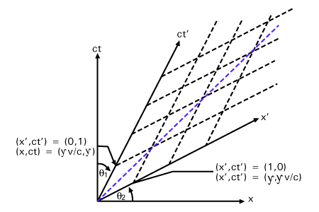
A Minkowski diagram or spacetime diagram is a convenient way of graphically representing the lorentz transformations between frames as a transformation of coordinates. They are especially useful for gaining a qualitative understanding of relativistic problems. We make a spacetime diagram by representing frame F as the coordinate axes x (horizontal) and ct (vertical). We are ignoring the y and z directions, since they are uninteresting. The plot of an object's x- position versus time on the Minkowski diagram is called its worldline. Notice that light, traveling one unit of ct for every unit of x will follow the line x = ct, inclined at a 45o angle.

 = γ
= γ from the origin, so the ratio of units on the ct' axis to those on the ct axis is
just this value, namely:
 = =  |
This approaches infinity as v→c and is one if v = 0. Similar analysis shows that the x' axis is an equal angle from the x-axis and that the ratio of units
 is also equal (see ). Thus, the faster F' relative to F, the more its coordinates are squished towards the
x = ct line.
The advantage of a Minkowski diagram is that the same worldline applies to both sets of coordinate axes (that is, to x and ct, as well as to x' and ct'). The Lorentz transformation is made by changing the coordinate system underneath the worldline rather than the worldline itself. In many situations this allows us to visualize the perspectives of the different observers more easily. If we had a very detailed and accurate Minkowski diagram we could use it to read off the values for Δx, Δct, Δx', and Δct'. To find the spacetime coordinates of an event in F, one can read the value off the x and ct axes; to find the coordinates in a moving frame the x' and ct' axes corresponding to the appropriate velocity can be constructed (using the angle formulas explained above), and the value read off using the units derived for x' and ct', above.


 payment page


