Please wait while we process your payment
If you don't see it, please check your spam folder. Sometimes it can end up there.
If you don't see it, please check your spam folder. Sometimes it can end up there.
Please wait while we process your payment

By signing up you agree to our terms and privacy policy.
Don’t have an account? Subscribe now
Create Your Account
Sign up for your FREE 7-day trial
By signing up you agree to our terms and privacy policy.
Already have an account? Log in
Your Email
Choose Your Plan
Individual
Group Discount
Save over 50% with a SparkNotes PLUS Annual Plan!
 payment page
Purchasing SparkNotes PLUS for a group?
Get Annual Plans at a discount when you buy 2 or more!
Price
$24.99 $18.74 /subscription + tax
Subtotal $37.48 + tax
Save 25% on 2-49 accounts
Save 30% on 50-99 accounts
Want 100 or more? Contact us for a customized plan.
 payment page
Your Plan
Payment Details
Payment Summary
SparkNotes Plus
You'll be billed after your free trial ends.
7-Day Free Trial
Not Applicable
Renews July 8, 2025 July 1, 2025
Discounts (applied to next billing)
DUE NOW
US $0.00
SNPLUSROCKS20 | 20% Discount
This is not a valid promo code.
Discount Code (one code per order)
SparkNotes PLUS Annual Plan - Group Discount
Qty: 00
SparkNotes Plus subscription is $4.99/month or $24.99/year as selected above. The free trial period is the first 7 days of your subscription. TO CANCEL YOUR SUBSCRIPTION AND AVOID BEING CHARGED, YOU MUST CANCEL BEFORE THE END OF THE FREE TRIAL PERIOD. You may cancel your subscription on your Subscription and Billing page or contact Customer Support at custserv@bn.com. Your subscription will continue automatically once the free trial period is over. Free trial is available to new customers only.
Choose Your Plan
This site is protected by reCAPTCHA and the Google Privacy Policy and Terms of Service apply.
For the next 7 days, you'll have access to awesome PLUS stuff like AP English test prep, No Fear Shakespeare translations and audio, a note-taking tool, personalized dashboard, & much more!
You’ve successfully purchased a group discount. Your group members can use the joining link below to redeem their group membership. You'll also receive an email with the link.
Members will be prompted to log in or create an account to redeem their group membership.
Thanks for creating a SparkNotes account! Continue to start your free trial.
We're sorry, we could not create your account. SparkNotes PLUS is not available in your country. See what countries we’re in.
There was an error creating your account. Please check your payment details and try again.
Please wait while we process your payment

Your PLUS subscription has expired
Please wait while we process your payment
Please wait while we process your payment

Galvanic Cells
Galvanic cells harness the electrical energy available from the electron transfer in a redox reaction to perform useful electrical work. The key to gathering the electron flow is to separate the oxidation and reduction half-reactions, connecting them by a wire, so that the electrons must flow through that wire. That electron flow, called a current, can be sent through a circuit which could be part of any number of electrical devices such as radios, televisions, watches, etc.
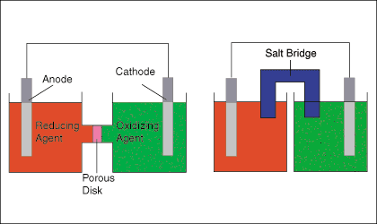
The figure below shows two typical setups for galvanic cells. The left hand cell diagram shows and oxidation and a reduction half-reaction joined by both a wire and a porous disk, while the right hand cell diagram shows the same cell substituting a salt bridge for the porous disk.

The salt bridge or porous disk is necessary to maintain the charge neutrality of each half-cell by allowing the flow of ions with minimal mixing of the half-cell solutions. As electrons are transferred from the oxidation half-cell to the reduction half-cell, a negative charge builds in the reduction half-cell and a positive charge in the oxidation half-cell. That charge buildup would serve to oppose the current from anode to cathode-- effectively stopping the electron flow--if the cell lacked a path for ions to flow between the two solutions.
The above figure points out that the electrode in the oxidation half-cell is called the anode and the electrode in the reduction half-cell is called the cathode. A good mnemonic to help remember that is "The Red Cat ate An Ox" meaning reduction takes place at the cathode and oxidation takes place at the anode.
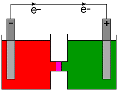
The anode, as the source of the negatively charged electrons is usually marked with a minus sign (-) and the cathode is marked with a plus sign (+). Physicists define the direction of current flow as the flow of positive charge based on an 18th century understanding of electricity. As we now know, negatively charged electrons flow in a wire. Therefore, chemists indicate the direction of electron flow on cell diagrams and not the direction of current. To make that point clear, the direction of electron flow is indicated on with a arrow and the symbol for an electron, e- .

Instead of drawing a cell diagram such as or chemists have devised a shorthand way of completely describing a cell called line notation. This notation scheme places the constituents of the cathode on the right and the anode components on the left. The phases of all reactive species are listed and their concentrations or pressures are given if those species are not in their standard states (i.e. 1 atm. for gasses and 1M for solutions). All phase interfaces are noted with a single line ( | ) and multiple species in a single phase are separated by commas. For example, a half-cell containing 1M solutions of CuO and HCl and a Pt electrode for the reduction of Cu2+ would be written as:
Please wait while we process your payment

