Conditions for Interference
Recall that light, which obeys the wave equation, must also obey the principle of superposition. In fact, both the electric and magnetic fields of the light in a region where two light waves overlap must be the vector sums of the individual electric and magnetic fields. Interference is collective name for the effects that occur when two or more light waves overlap to give an irradiance that is different from the sum of the component irradiances. The irradiance is defined as the average energy per area per unit time falling on a surface. It is proportional to the square of the amplitude of the light wave:
I = < S > =  = ε0c < E2 > = = ε0c < E2 > =  |
where < F > denotes the time average of F, and E0 is the amplitude of the electric field vector. The irradiance is a very useful concept to use because it can be easily measured by a range of optical instruments (including our eye--irradiance is a measure of the 'brightness' we perceive).
When we have a single light wave the value of < E2 > is just given by < E.E >. However, if two electric field vectors E1 and E2 overlap at a point we have < E2 > = < (E1 + E2).(E1 + E2) > from the principle of superposition. Since < (E1 + E2).(E1 + E2) = E12 + E22 +2E1.E2, we can write:
| < E2 > = < E12 > + < E22 > +2 < E1.E2 > |
The last term is called the interference term. We can evaluate that term in the case of harmonic waves as:
| E1.E2 | = E01.E02cos(k1x - σt + ε1)cos(k2x - σt + ε2) | ||
| = E01.E02[cos(k1x + ε1)cos(σt) + sin(k1x + ε1)sin(σt)] | |||
| ƒ[cos(k2x - ε2)cos(σt) + sin(k2x - σt)sin(σt)] |
Where ε1 and ε2 are arbitrary phase constants. Taking the time average and using the fact that < cos2(σt) > = < sin2(σt) > = 1/2 and < sin(σt)cos(σt) > = 0 we find:
| < E1.E2 > = 1/2×E01.E02cos(k1x + ε1 - k2x - ε2) |
But the argument of the cosine is just the phase difference between the two waves, arising from their initial phase offset (εs) and their different path lengths (the distance they took to reach the point). Thus we can write this as:
| 2 < E1.E2 > = E01.E02cosδ |
Since < E12 > =
 and recalling that irradiance is proportional to
< E2 > we can write an expression for the total irradiance at a point as:
I = I1 + I2 +2 cosδ cosδ |
since I1 = εc < E12 > and 2 < E1.E2 > = 2εc
 .
.
Thus at various points in space the irradiance can be greater than, equal to or less that I1 + I2 depending on δ. Maxima (total constructive interference) occur where cosδ = 1, or where the component waves are completely in-phase. Minima (total destructive interference) occur where cosδ = - 1 and the phase difference is an odd multiple of ±Π. When the amplitudes of the two overlapping waves are equal (E01 = E02) we have I1 = I2 = I0 and:
| I = 2I0 +2I0cosδ = 4I0cos2(δ/2) |
For two beams to interfere to produce a stable pattern, they must have very nearly the same frequency. If this is not the case, δ would vary very rapidly in time and the interference term would average to zero over time. However, two white light (polychromatic) beams will produce an interference pattern since blue will interfere with blue, yellow with yellow, etc. For the clearest patterns waves should also have equal amplitudes; this allows complete destructive interference when the waves are out of phase. The sources, however, needn't be in-phase with one another, however, the phase difference between them must remain constant; such sources are said to be coherent.
Young's Experiment
The macroscopic result of the interference term is that interfering sources create a pattern of varying brightness on an appropriately placed screen. This may be caused either by the two sources being out-of-phase with one another or by the two sources traversing paths of different lengths to a particular point on the screen. Path lengths that vary by amounts of the order of a fraction of the wavelength of the light cause arriving waves to be out-of-phase with one another (for example if the path lengths of in- phase sources differ by λ/2 a peak will arrive with a trough and destructive interference will result) and interfere. The light and dark zones created by an two of more interfering waves are called fringes.
One of the simplest and most important examples of this effect is an experiment, first performed by Thomas
Young in 1805 to prove that light had a wave nature. He shined sunlight through a single pinhole to create
one coherent beam which he then shone through two slit-shaped apertures. The cylindrical waves emerging
from these slits comprise coherent, in-phase sources. Another alternative is to use plane waves
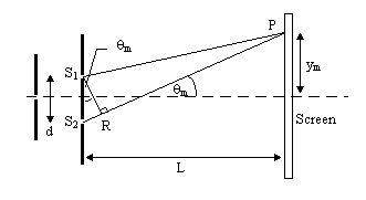
from a laser to illuminate the apertures. Young's arrangement is shown in .

 θm to write: S1B
 aθm. But sinθm
 θm
θm ym/L and this implies S1B
 aym/L.
Now, constructive interference will occur when S1B is equal to a whole number of wavelengths. So for
an integer m, S1B = mλ so the position of the bright fringes is given by:
ym  |
The angular position of the fringes is given by:
sinθm =  |
or θm
 mλ/d. The spacing between fringes is given by:
ym+1 - ym  - -    |
Since red light has a greater wavelength than blue light, red fringes must be broader. Note that the region in the center of the screen, between the slits is a bright maximum, called the zeroth order fringe corresponding to m = 0. The phase difference at any point is given by δ = k(S1B) where k = 2Π/λ. If the beams both have irradiance I0 the irradiance at any point is given by:
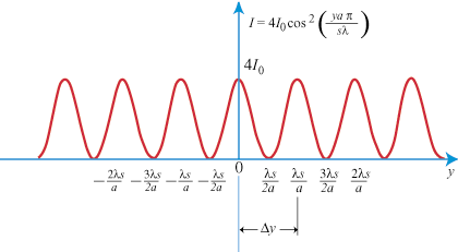
I = 4I0cos2   = 4I0cos2 = 4I0cos2   |
It is worth bearing in mind that these results are an idealization assuming an infinitesimally small width of the slits. A full treatment of the situation, accounting for the finite width of the slits requires us to take diffraction into account. A plot of irradiance against position for Young's experiment is shown in .

Interferometers
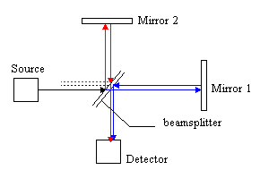
Interferometers are devices that employ the effects of interference to make very accurate measurements.
The most famous of these is called a Michelson interferometer, which was used to measure the wavelength
of lines in atomic spectra.


