Thin Lenses
When the size of the physical and optical objects of a system are much larger than the wavelength of the light (or as λ→ 0), we are in the realm of geometrical optics. Optical systems in which the wave nature of light must be taken into account (interference, diffraction) are called physical optics. Of course, every real system experiences diffraction effects, so geometric optics is necessarily an approximation. However, the simplicity arising from treating only rays which move in straight lines affords many uses.
A lens is a refracting device (a discontinuity in the medium) that redistributes the energy being
propagated by electromagnetic radiation. This is usually achieved by re-shaping the wavefront, most
usefully by turning spherical waves into plane waves and vice-versa. Lenses that cause an
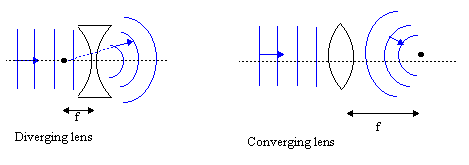
incoming plane wave to bend towards the axis through its middle are called converging or convex
lenses. They are thicker at their midpoint than at their edges. Concave lenses, on the
other hand, are thicker at their edges than in the middle; they cause an incoming plane wave to bend away
from its central axis and are hence also known as a diverging lenses. Both of these are illustrated
in .

Lenses that have only two refracting surfaces are called simple. Also, lenses that have a thickness that is negligible compared to the overall path length of the light traversing them are called thin. Here we will only consider thin, simple lenses. To first-order, the focal length of such a lens is given by:
 = (nl -1) = (nl -1)  - -   |
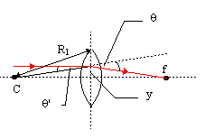
where nl is the index of refraction of the lens, R2 is radius of curvature of the left surface (from which the light approaches), and R1 is the radius of curvature of the right surface (through which the light leaves the lens). This is known as the lens-maker's equation. We can derive it by considering a spherical wave emanating from the center of the sphere with the same radius R1 as one side of the lens. From it is clear that tanθ' = y/R1.

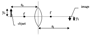
By far the most important formula in geometrical optics, however, relates the position of an object placed in
front of a lens to the position of its image, formed by the lens. In the
distance between the object and the lens is so and the distance between the lens and the image
is si.

 + +  = =  |
There are certain sign conventions to be applied with this formula, and with those to follow. so > 0 if the object is on the same side of the lens as the direction from which the light is coming, so < 0, otherwise. f > 0 if the focal point is on the opposite side of the lens to that from which the light is coming. si < 0 if the image is on the opposite side of the lens to that from which the light is coming. R > 0 if the center of the sphere is on the opposite side of the lens to that from which the light is coming. The height of an object, yo, or its image, yi, is considered positive if it lies above the optical axis (the central axis or axis of symmetry of the lens). Note that a planar interface has a focal length of infinity. The "transverse magnification" of a thin lens is given by:
MT =  = - = -  |
From the sign conventions, MT > 0 implies that the image is upright, while MT < 0 implies that it is inverted.
Mirrors
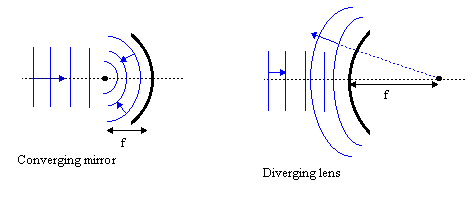
There are also two basic types of spherical mirrors. Concave mirrors reflect incoming plane waves to
a focal point directly in front of the mirror (they are converging mirrors). Convex mirrors
reflect incoming plane waves into outward-moving spherical waves with the center of the sphere
appearing to be behind the mirror (they are diverging mirrors).

 , where R is the radius of curvature of the mirror.
Also the very same relation between the image and object distances applies:
 = =  + +  |
Applying the sign conventions that f, so, and si are positive in front of the mirror, f > 0 for concave mirrors and f < 0 for convex mirrors. Note that images for which si is positive are called real images, and are those for which a screen can be placed at the position of the image in order to observe it; images for which si is negative are called virtual. No virtual image can be formed on a screen--any image seen in a mirror is an example of a virtual image. An alternative formulation of these definitions is to say that for real images light rays really do pass through where the image forms; for virtual images light rays only appear to be coming from the position of the image.
Mirrors have an advantage over lenses in that they do not suffer chromatic aberration. This
phenomenon arises due to dispersion, causing the lens to have not just one focal length
but a small band of focal lengths corresponding to the different amounts by which it refracts the different
colors. This means that it is impossible to focus colored images precisely with a lens. Mirrors, because they
do not rely on refraction, do not suffer this problem. Moreover, it is important to remember that all the
formulas we encountered here were derived using the first order approximation to the sine function
appearing in Snell's Law: sinθ θ. Of course this ignores higher order terms in
θ3, etc. Corrections arising from this and other considerations cause aberrations (or deviations)
from the simple equations developed here for spherical lens and mirror systems. In fact, there are five
primary, monochromatic aberrations called spherical aberration, coma, astigmatism, field curvature,
and distortion. They are collectively known as the Seidel aberrations.


 payment page


